
Switch Starting Pressure Explained: Matching 1.2, 1.5 and 2.2 bar Settings to Your Pump Curve
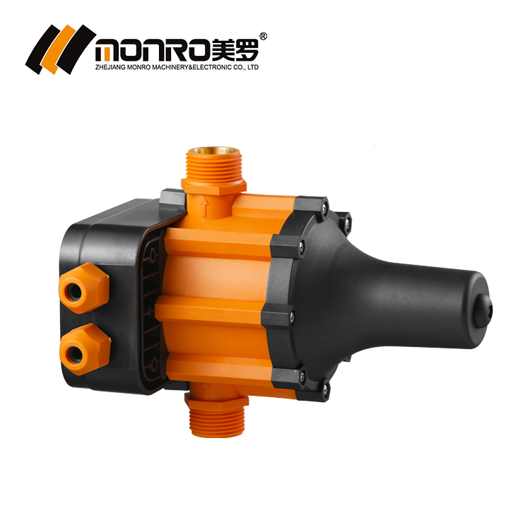
Starting pressure is the pressure at which an automatic pump controller energises the pump. Across the Monro EPC series it is normally a fixed factory setting of 1.2 bar, 1.5 bar or 2.2 bar — approximately 17, 22 and 32 PSI — with adjustable versions available when one fixed value cannot cover every installation on a project. The value you choose has to sit below the shut-off head of the pump and above the static head created by the highest outlet in the system. Miss on either side and the outcome is predictable: a pump that never reaches cut-out, rapid start/stop cycling, or fixtures that lose pressure the moment a second outlet opens.
This guide works the problem backwards from the pump curve: what each of the three settings means in PSI and metres of head, how much pump head it demands, which EPC models carry it, how to commission it, and when a fixed setting should be replaced by an adjustable or wide-range controller.
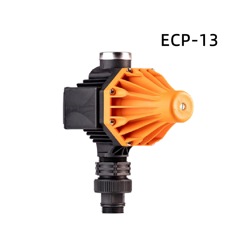
What Starting Pressure Controls — and What It Does Not
An automatic pressure control has two pressure thresholds, not one. Starting pressure (cut-in) is the pressure at which the controller closes the circuit and energises the pump. Stopping pressure (cut-out) is the pressure at which it opens the circuit and stops the pump. Monro describes the operating logic of the EPC application range in exactly these terms: the controller automatically starts and stops the pump in response to system pressure changes, activating it at the preset low-pressure setpoint and deactivating it at the high-pressure setpoint.
The starting movement itself is hydraulic: when a tap opens, line pressure falls; once the actual line pressure drops below the controller's starting pressure value, the controller starts the pump.
Fixed starting pressure vs two separate thresholds
On a fixed-setting EPC controller, the starting pressure is selected at order — 1.2 bar, 1.5 bar or 2.2 bar — and the pump is then stopped on flow: when the tap closes, the controller can no longer detect water flow and switches the pump off. On adjustable and digital models the two thresholds can be separated and set independently. The EPC-10, for example, has a 0.5–9.3 bar starting pressure setting and a 0.7–9.5 bar stopping pressure setting. The EPC-12 offers 0.5–6.7 bar starting and, in its second mode, 0.8–7.0 bar stopping. The EPC-17 stops between 0.7 bar and 9.5 bar in its manual mode.
Starting pressure is a trigger, not a performance rating
A 1.5 bar setting does not mean the switch delivers 1.5 bar at the shower head. It means the switch waits for line pressure to fall to 1.5 bar before it starts the pump. Everything above that value has to be produced by the pump, the impeller and the pipe run. This is the single most common source of mis-specified projects: buyers treat the starting pressure figure as a pressure guarantee, when it is only an activation threshold.
Why a Mismatched Starting Pressure Fails
The selection rule published for the Monro EPC range is short and quantitative: the pump head must be at least 0.8 bar higher than the start-up pressure of the pressure controller. Two numbers therefore govern the choice — the starting pressure setting and the shut-off head of the pump on its curve.
The 0.8 bar margin and the 10 m rule
Working in head rather than pressure makes the decision concrete. At a starting pressure of 1.2 bar, the maximum water use height is 1.2 × 10 m = 12 m of usable height, and the pump lift must be at least (1.2 + 0.8) × 10 m = 20 m. The same arithmetic carries through to the other two settings. That single relationship is what ties the switch rating to the pump curve, and it is why the same controller model can be correct on one site and wrong on the next.
Two predictable failure patterns
- Setting too high for the pump. If the pump's shut-off head is below the starting pressure, the controller commands the pump to run but the line never reaches the pressure needed for normal cycling. The pump runs on, and on models equipped with run-dry protection the failure indication can appear when the controller fails to detect the expected flow or pressure condition.
- Setting too low for the installation. The pump starts at a pressure below what the highest or most remote outlet needs, so the top of the system starves. Where the pump is stopped on flow detection, a low trigger combined with a small pressure vessel produces rapid start/stop cycling and unnecessary motor starts.
Industry Background: Units, Standards and Market Structure
The dual-unit problem behind this topic is structural, not accidental. Fortune Business Insights valued the global pressure switch market at USD 3.2 billion in 2025, and Market Research Future reported that electromechanical pressure switches accounted for approximately 62% of global market share in 2024, with solid-state electronic switches taking the balance. That split appears directly in product catalogues: mechanical KRS switches are typically specified in PSI ranges such as 20–40 PSI, 30–50 PSI and 40–60 PSI, while electronic EPC controllers are specified in bar. A buyer converting a mechanical installation to an electronic controller, or quoting one line of switches across both families, has to translate between the two systems without losing the setting that the pump curve actually requires.
The standards layer
IEC 60730-2-6:2025 is the current international standard for automatic electrical pressure sensing controls. In the EU market, safety certification for this product family runs through EN 60730-1:2016+A1+A2 and EN 60730-2-6:2016+A1, while electromagnetic compatibility is demonstrated against EN IEC 55014-1:2021, EN IEC 55014-2:2021, EN 61000-3-2:2019+A1 and EN 61000-3-3:2013+A1+A2 under Directive 2014/30/EU. Water pump pressure switches are commonly traded under HS Code 853650.
The supplying entity
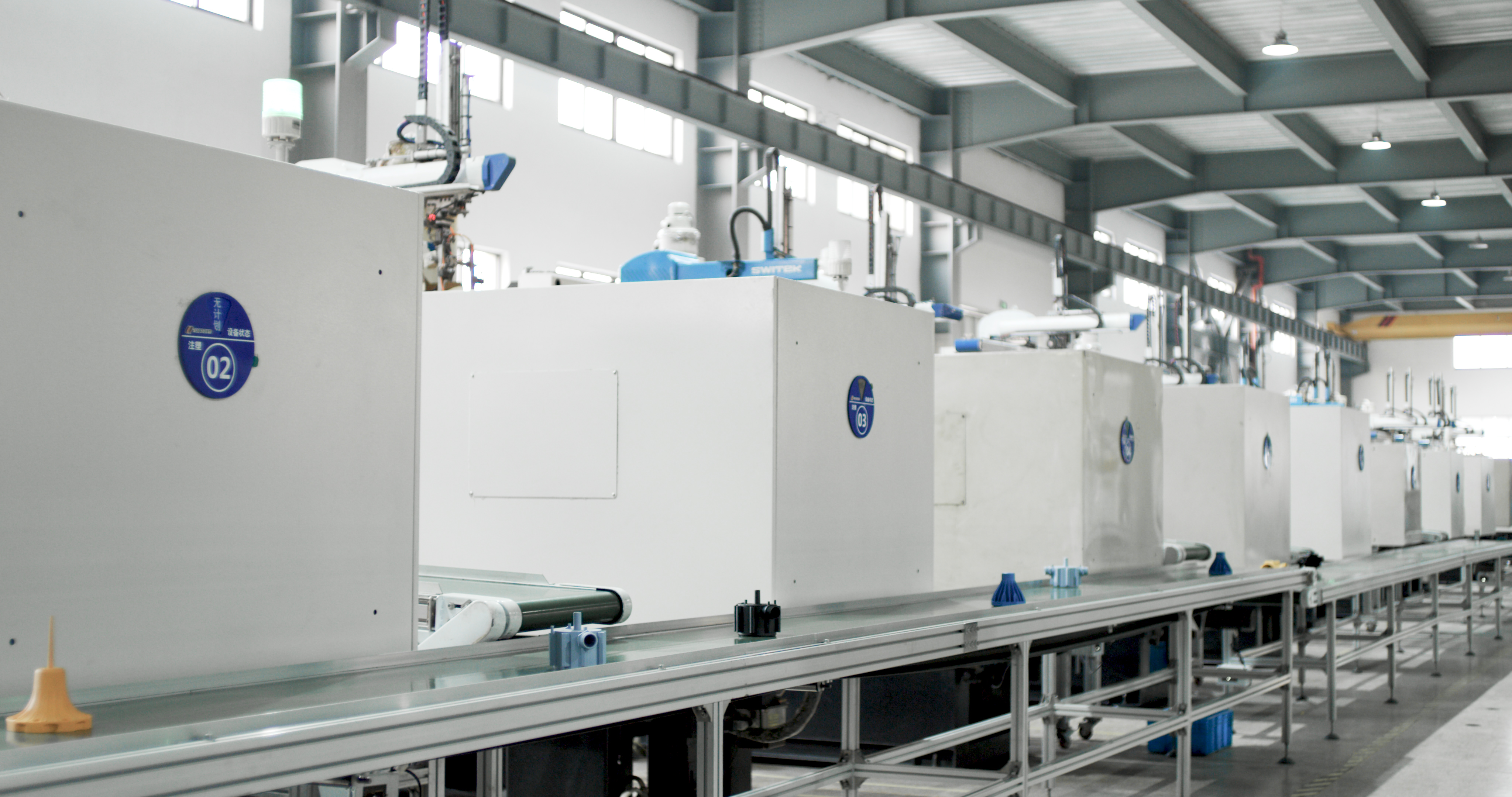
Zhejiang Monro Machinery & Electronic Co., Ltd. (Monro Switch) is a manufacturer of pressure controllers, pressure switches and float switches based in Wenling City, Zhejiang Province, China — a coastal city with a developed industrial base. Officially established in 2010, the company draws on more than 20 years of manufacturing expertise in pressure controls and float switches. It operates a 30,000 m² facility with a workforce of 200 and a 10-engineer R&D team, offers more than 40 models of pressure controllers for water pump systems and air compressors, and exports about 90% of its output to Asia, Europe, North and South America, and the Middle East and Africa. Its quality system is certified to ISO 9001:2015.
Matching 1.2, 1.5 and 2.2 bar to PSI and Metres of Head
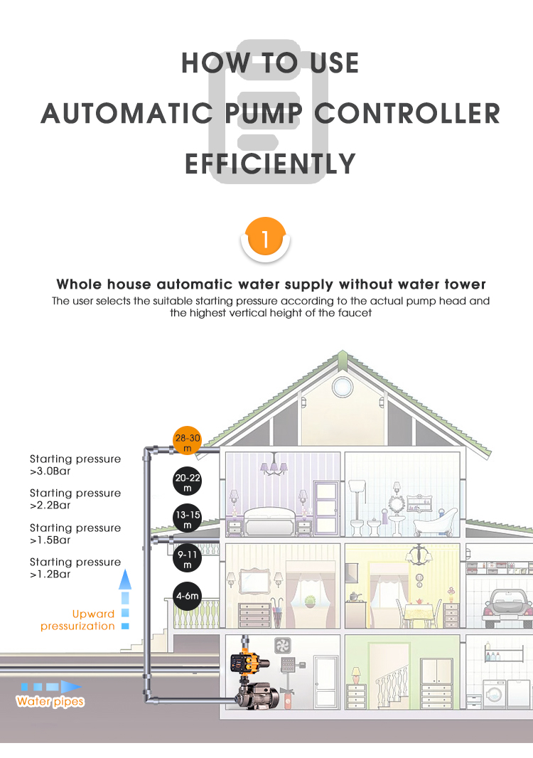
Because one bar equals approximately 14.5 PSI, the three EPC settings translate to roughly 17 PSI, 22 PSI and 32 PSI. Applied to the 0.8 bar margin rule and the 10 m per bar head relationship, each setting defines a service ceiling and a minimum pump head.
| Starting pressure | PSI equivalent | Maximum water use height | Minimum pump head required | Typical system condition it suits |
|---|---|---|---|---|
| 1.2 bar | approx. 17 PSI | 12 m | 20 m | Low-lift domestic supply where the highest outlet is close to the switch and the pump curve is modest |
| 1.5 bar | approx. 22 PSI | 15 m | 23 m | Multi-level supply or longer pipe runs with additional fittings and friction losses |
| 2.2 bar | approx. 32 PSI | 22 m | 30 m | Taller buildings, extended horizontal mains, or fixtures that need a firmer minimum supply pressure |
The 0.8 bar margin is the published Monro rule and applies to the starting pressure setting, not to the pump's nominal rating. Always read it against the shut-off head on the actual pump curve, not against the maximum head printed on the nameplate alone.
Worked example at 1.2 bar
For a starting pressure of 1.2 bar, the maximum water use height is 12 m, and the pump lift must be at least 20 m. A surface pump whose curve shows shut-off head close to 20 m and which is asked to serve outlets within 12 m of the controller is correctly matched at the 1.2 bar setting. The same pump moved to an installation with 18 m of vertical rise is not: the trigger is now above the static head the system generates, and the pump will run without settling into a normal start/stop rhythm.
Worked example at 1.5 bar and 2.2 bar
At 1.5 bar the ceiling becomes 15 m and the minimum pump head 23 m; at 2.2 bar the ceiling becomes 22 m and the minimum pump head 30 m. In practice, the higher the setting, the deeper the pump curve has to be, and the more important it becomes to allow for friction losses in long pipe runs and for the pressure drop across filters and check valves. This is the point at which many projects stop using a single fixed value and move to an adjustable controller.
Selecting the Setting: Which EPC Model Carries Which Configuration
The three fixed settings are shared across a wide part of the EPC range, so model selection usually starts with power rating, protection class and connection thread rather than with the pressure value itself. The table below lists the published configurations.
| Model | Starting pressure setting | Adjustable range | Max. motor power | Protection | Connection thread |
|---|---|---|---|---|---|
| EPC-1 / EPC-1.1 | 1.2 / 1.5 / 2.2 bar | 1.2–2.5 bar (adjustable version) | 1.1 / 1.5 / 0.75 kW | IP65 | G1″, G1 1/4″, G1 1/2″, NPT1″ |
| EPC-2 | 1.2 / 1.5 / 2.2 bar | — | 1.1 / 1.5 / 0.75 kW | IP65 | R1″ |
| EPC-2.1 | 1.2 / 1.5 / 2.2 bar | 1.5–3.0 bar | 0.55 / 1.1 / 1.5 / 0.75 kW | IP44 | R1″ |
| EPC-3 | 1.2 / 1.5 / 2.2 bar | 1.2–2.5 bar | 0.55 / 1.1 / 1.5 / 0.75 kW | IP65 | G1″ |
| EPC-3P | 1.2 / 1.5 / 2.2 bar | 1.2–2.5 bar | 0.55 / 1.1 / 1.5 / 0.75 kW | IP65 | G1″ |
| EPC-5 | 1.2 / 1.5 / 2.2 bar | 1.2–2.5 bar | 0.55 / 1.1 / 1.5 / 0.75 kW | IP65 | G1″, NPT1″ |
| EPC-5.1 | 1.2 / 1.5 / 2.2 bar | 1.2–2.5 bar | 0.55 / 1.1 / 1.5 / 0.75 kW | IP44 | G1″, NPT1″ |
| EPC-7 | 1.2 / 1.5 / 2.2 bar | 1.2–2.5 bar | 2.2 / 1.1 / 4 kW | IP65 | G1″, G1 1/4″, G1 1/2″ |
| EPC-13 | 1.2 / 1.5 / 2.2 bar | 1.2–2.5 bar | 1.5 / 0.75 kW | IP65 | G1″, G1 1/4″ |
| EPC-14 / EPC-14A | 1.2 / 1.5 / 2.2 bar | — | 1.5 / 0.75 kW | IP65 | G1″ |
| EPC-15 | 1.2 / 1.5 / 2.2 bar | — | 1.1 / 1.5 / 0.75 / 0.55 kW | IP65 | G1″ |
| EPC-16 | 1.2 / 1.5 / 2.2 bar | — | 1.5 / 0.75 kW | IP65 | G1″ |
| EPC-10 | 0.5–9.3 bar (settable) | Via digital setting | 2.2 / 1.1 kW | IP65 | Female 1/4″, 3/8″; male 1/4″, 1/2″ |
| EPC-12 | 0.5–6.7 bar (settable) | Via digital setting | 2.2 / 1.1 kW | IP65 | Female G1″ |
| EPC-17 | Mode 1: auto 70% of pipe pressure; Mode 2: cut-in 0.5–9.3 bar | 0.5–9.3 bar | 1.1 / 2.2 kW | IP65 | G1″ |
Adjustable ranges are shown only where they are published for the model concerned. Several models are offered in either an adjustable or a non-adjustable version, which allows a distributor to hold one body type and cover both fixed-setting and trim-on-site demand.
When flexibility is worth paying for: the 1.5–3.0 bar option
The clearest case for an adjustable controller is a project where the same pump model is installed at different elevations. A fixed 1.2 bar unit cannot be pushed to 2.2 bar on the taller riser, so two stock-keeping lines are needed. The EPC-2.1 removes that problem: it carries an adjustable starting pressure range of 1.5–3.0 bar, with inlet and outlet at 90 degrees and a built-in socket that simplifies wiring. Other adjustable options include the EPC-1, EPC-3, EPC-3P, EPC-5, EPC-5.1, EPC-7 and EPC-13, all published with a 1.2–2.5 bar adjustable starting pressure, and the digital EPC-10, EPC-12, EPC-12P and EPC-17, which allow far wider settings plus time-based operation.
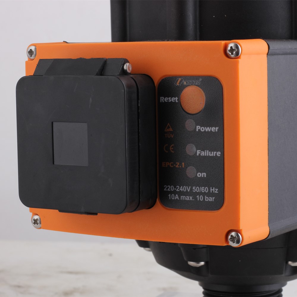
Where a system has genuinely variable demand — a building with peaks driven by irrigation cycles, or a booster set that must also fill a tower — the wider electronic settings change the nature of the decision. The EPC-10 sets starting pressure anywhere from 0.5 bar to 9.3 bar and stopping pressure from 0.7 bar to 9.5 bar; the EPC-12 uses 0.5–6.7 bar starting with a maximum working pressure of 8 bar; the EPC-17 can derive its starting pressure automatically at 70% of pipe pressure in its first mode.
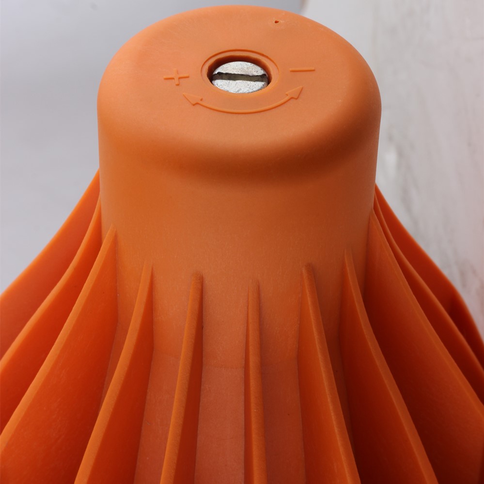
Step-by-Step: Selecting and Commissioning the Setting
- Measure the maximum water use height. Take the vertical distance from the controller to the highest outlet it must serve, and add the equivalent head for friction in long runs and fittings. This figure must stay under the ceiling of the chosen setting: 12 m at 1.2 bar, 15 m at 1.5 bar, 22 m at 2.2 bar.
- Read the pump curve at the duty point. Identify the shut-off head and the head at the expected flow. The shut-off head must exceed the starting pressure by at least 0.8 bar — 20 m, 23 m or 30 m of total pump lift for the three settings respectively.
- Confirm the flow the system actually draws. A setting that looks acceptable on shut-off head alone can still fail if the pump runs far out on its curve at peak draw and the developed head collapses toward the trigger value.
- Check the motor power against the controller rating. Every EPC model publishes a maximum power envelope — 0.55–1.5 kW across most of the fixed-setting range, 2.2 kW for the EPC-10, EPC-12 and EPC-17, and up to 4 kW for the EPC-7. The pump must fall inside it.
- Decide fixed or adjustable. Use 1.2, 1.5 or 2.2 bar where the installation is known and repeatable. Move to a 1.2–2.5 bar or 1.5–3.0 bar adjustable model where elevation varies across the project, and to a digital model where starting and stopping pressures must be set independently.
- Verify environmental and connection compatibility. IP65 covers most EPC models; IP54 applies to the EPC-9 and EPC-11A, and IP44 to the EPC-2.1 and EPC-5.1. Maximum working temperature is 55 °C on the EPC-1 series and 60 °C on the EPC-9, EPC-10, EPC-12, EPC-13, EPC-14, EPC-15, EPC-16, EPC-17 and EPC-19. Threads range from G1″ to G1 1/2″ and NPT1″ by model.
- Commission in the correct order. Test the pump separately first and confirm that the nameplate parameters match the controller. Install the controller following the direction of the arrow on its housing. Connect the controller to a dedicated plug line and seal every joint with waterproof insulating tape. Then open the main outlet valve and all faucets before switching on the power supply, so the controller starts into an open system.
Use Cases: Three Settings, Three System Profiles
1.2 bar — compact domestic supply
A ground tank with a small surface pump feeding a single group of outlets close to the controller is the classic 1.2 bar application. With a 12 m service ceiling and a 20 m minimum pump head, this setting keeps the pump operating on a comfortable part of its curve and avoids unnecessary pressure in the pipework. It is also the setting to avoid where the highest outlet creeps above the 12 m ceiling during renovation.
1.5 bar — multi-level and longer runs
Adding a storey, extending the run, or introducing filtration pushes the required head past what the 1.2 bar setting can reliably serve. At 1.5 bar the ceiling rises to 15 m and the minimum pump head to 23 m, which suits taller houses and small pressure-boosting duties. Models such as the EPC-14, described as mainly used for non-tower water supply, are commonly specified in this band, with built-in run-dry protection and a check valve.
2.2 bar — tall buildings and extended mains
At 2.2 bar the service ceiling reaches 22 m with a minimum pump head of 30 m. This is the setting for installations where outlets are far above or far away from the switch, or where the fixtures themselves need a firmer minimum supply. Because it demands more from the pump curve, it is also the setting most likely to require verification against the actual curve rather than the nameplate rating.
Wide-range and set-and-forget systems
Where the same controller must serve a tower fill cycle as well as live demand, a digital model changes the workflow. The EPC-12P and EPC-17 add time settings of 0.1–1 hour and 1–24 hours, which allows the pump to be scheduled to fill a tower at set times based on consumption. The EPC-11A pairs a 0.5–9.3 bar starting pressure setting with a built-in pressure gauge, so the line pressure can be read directly during commissioning.
Field evidence from a retail installation
One Monro retail customer in China has been running Monro automatic pressure controls for two years on a 50-piece installation serving agriculture irrigation, water treatment and construction duties. The stated result is reliable automatic pressure control for the water supply system, with the automatic pump start/stop function as the key requirement. That is the practical test of any starting pressure decision: not a single perfect number, but a setting that holds stable across seasons and duty cycles.
Compliance: What to Verify Before You Specify a Setting
A starting pressure decision is only useful if the controller carrying it can legally enter the target market. For the EPC family, the relevant documents are specific and checkable. The CE-EMC Certificate of Conformity with certificate number AE505724390001, issued under TÜV Rheinland LGA Products GmbH, covers EPC-1, EPC-2, EPC-2.1, EPC-3, EPC-3P, EPC-4, EPC-5 and EPC-15 for the EU market. Certificate number AE0604425 0001 covers EPC-10, EPC-12 and EPC-16, and certificate number AE505987560001 covers EPC-14. On the safety side, the TÜV Rheinland Safety Certification with certificate number R 50175890 covers EPC-10, EPC-12, EPC-14 and EPC-16 against EN 60730-1:2016+A1+A2 and EN 60730-2-6:2016+A1.
For North America, the mechanical KRS-4 pressure control switch is UL Listed under certificate number E316396, issued by UL LLC, based on the pressurer operated switch scope. Manufacturing is covered by an ISO 9001:2015 system certification, certificate number 20126Q00115R300, issued by BeiJing ZHONGRUI Unite against GB/T19001-2016/ISO9001:2015.
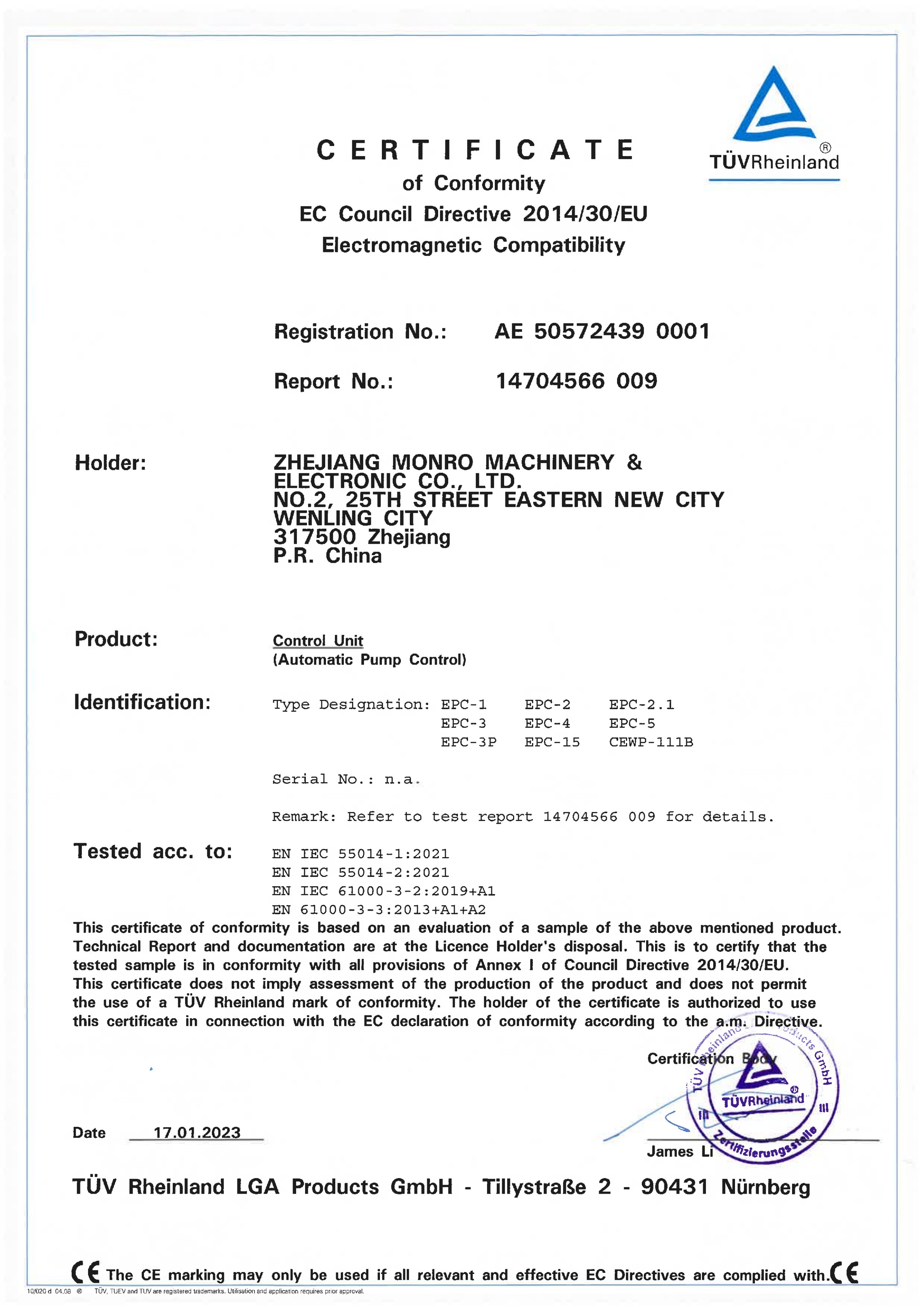
Because a certificate is issued against a named model list, the correct purchasing habit is to open the certificate and confirm that the exact model being quoted appears on it, rather than accepting a generic statement that a supplier is "CE certified".
Frequently Asked Questions
How can I confirm that a pressure control switch manufacturer's CE certification is genuine and covers my model?
Ask for the certificate number and the model list printed on the certificate, then check that your exact model appears on it. For the Monro EPC family, the CE-EMC Certificate of Conformity number AE505724390001 covers EPC-1, EPC-2, EPC-2.1, EPC-3, EPC-3P, EPC-4, EPC-5 and EPC-15; number AE0604425 0001 covers EPC-10, EPC-12 and EPC-16; number AE505987560001 covers EPC-14. All of these are issued by TÜV Rheinland LGA Products GmbH against EN IEC 55014-1:2021, EN IEC 55014-2:2021, EN 61000-3-2:2019+A1 and EN 61000-3-3:2013+A1+A2 under Directive 2014/30/EU. Safety certification number R 50175890 covers EPC-10, EPC-12, EPC-14 and EPC-16 against EN 60730-1:2016+A1+A2 and EN 60730-2-6:2016+A1.
How do I decide between 1.2 bar, 1.5 bar and 2.2 bar starting pressure?
Decide from head, not from habit. The maximum water use height supported by each setting is 12 m at 1.2 bar, 15 m at 1.5 bar and 22 m at 2.2 bar. The matching minimum pump head is 20 m at 1.2 bar, 23 m at 1.5 bar and 30 m at 2.2 bar, because the pump head must be at least 0.8 bar above the start-up pressure. Choose the lowest setting that still covers the highest outlet plus friction losses; if the pump curve cannot deliver the required head at the higher setting, an adjustable or digital model is the correct answer rather than a fixed unit.
What are the commercial constraints — minimum order quantity and customization?
Monro produces on an OEM basis with a minimum order quantity of 204 pieces and a production lead time of 45 days. Customization options include cable length, cable material, brand customization, colour box customization and colour customization, and pressure settings can be customized to customer requirements. Monthly capacity is 180,000 pieces for automatic pump controls in the EPC series, 250,000 pieces for KRS pressure switches and 30,000 pieces for float switch and liquid level controls. After-sales support is remote, with a one-year warranty.
Can the starting pressure setting be validated before a production order is released?
Validation starts with data rather than hardware. Confirm the pump's shut-off head and duty-point head, compare them to the 20 m, 23 m or 30 m minimum for the setting you intend to use, then confirm the motor power falls inside the model's maximum power envelope. Where the setting needs to be locked to a specific value for the project, Monro customizes pressure settings to customer requirements, and every unit is 100% tested before shipment. For projects with mixed elevations, selecting an adjustable model such as the EPC-2.1 (1.5–3.0 bar) or an EPC unit with a 1.2–2.5 bar adjustable range removes the need to validate a single fixed value at all.
How fast can a matched order be supplied, and what is the next step?
Standard lead time is 45 days, supported by monthly capacity of 180,000 EPC units, 250,000 KRS units and 30,000 FPS/STSW units. The fastest way to close a specification is to send the pump curve and the maximum water use height with the enquiry, so the setting can be confirmed against the 0.8 bar margin rule before the order is placed. The full model list, thread options and protection ratings are collected in the Monro catalogue 2025 (PDF), and model-level questions can be sent directly to the team.
Need the setting matched to a specific pump curve? Send the pump model, the shut-off head and the maximum water use height to the Monro Switch engineering team, and confirm whether a fixed 1.2 / 1.5 / 2.2 bar unit or an adjustable controller fits the installation.
Website: www.monroswitch.com | Email: sale@monro-switch.com | Tel / WhatsApp: +86 13586289715
Zhejiang Monro Machinery & Electronic Co., Ltd. — No.2, 25th Street, Eastern New City, Wenling City, Zhejiang Province, China.
Conclusion
The 1.2, 1.5 and 2.2 bar settings on the Monro EPC range are not interchangeable preferences; they are three different hydraulic commitments. Each one defines a maximum water use height (12 m, 15 m, 22 m) and a minimum pump head (20 m, 23 m, 30 m) that the pump curve has to satisfy. The setting is correct when the highest outlet stays inside the ceiling and the pump can still develop 0.8 bar more than the trigger value at the duty point. Where a project mixes elevations or needs independent starting and stopping thresholds, the answer is an adjustable controller — the EPC-2.1 at 1.5–3.0 bar, the 1.2–2.5 bar adjustable versions across the EPC-1, EPC-3, EPC-3P, EPC-5, EPC-7 and EPC-13, or a digital model with a 0.5–9.3 bar range.
Have Questions or Need More Details?
Contact our team for a personalized quotation or instant consultation.
Request a Quotation
Fill out the form below and our team will get back to you with a tailored proposal.
WhatsApp Direct Chat
Prefer to chat in real-time? Message us on WhatsApp for instant assistance & quick answers.
- Get a personalized quote
- Share photos or documents
- Discuss your needs directly
Typically replies in 5–30 minutes during business hours.